
Product

Leak Detector
Detail
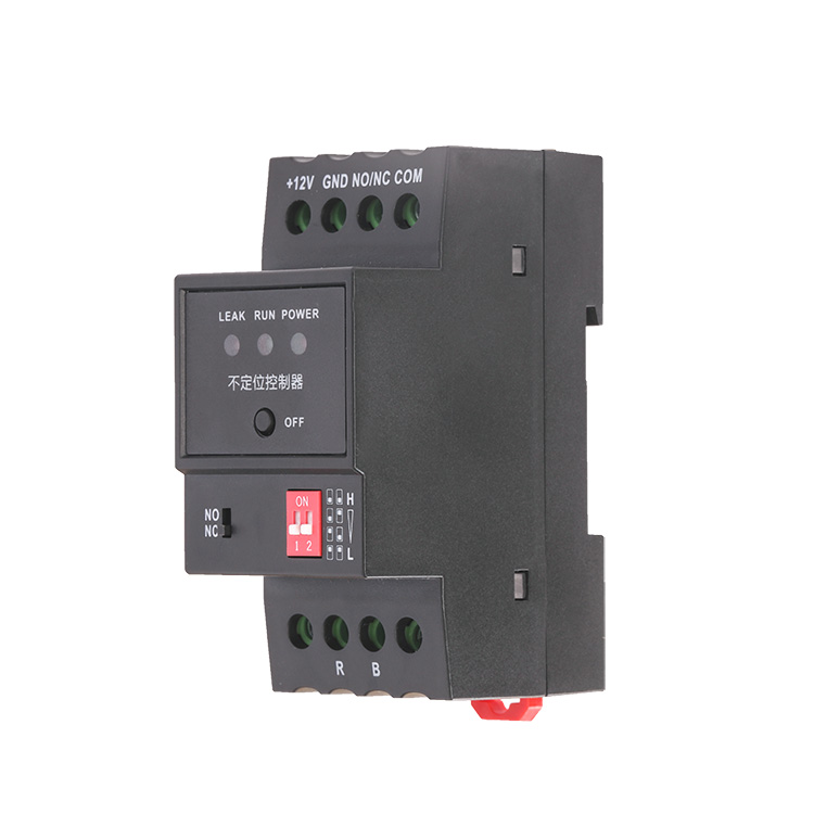
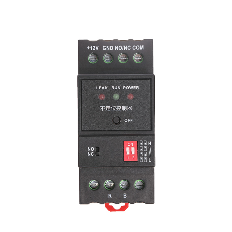
Product OverviewXW-DC-02 Simple leak detector is a simple and cost-effective liquid leak detection device, which can select different sensitivity through the dip switch on the panel to adapt to different detection environment and grade requirements.The relay contact signal output by the detector can be integrated with various monitoring systems to realize remote monitoring.
Application & Features
IDC
Data centre
Library
Museum
Warehouse
FeaturesUsing industrial-grade electronic components can not only ensure high sensitivity, but also reduce false alarms caused by various external factors.
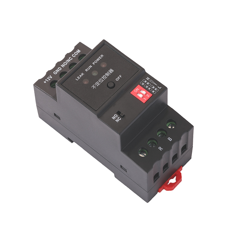
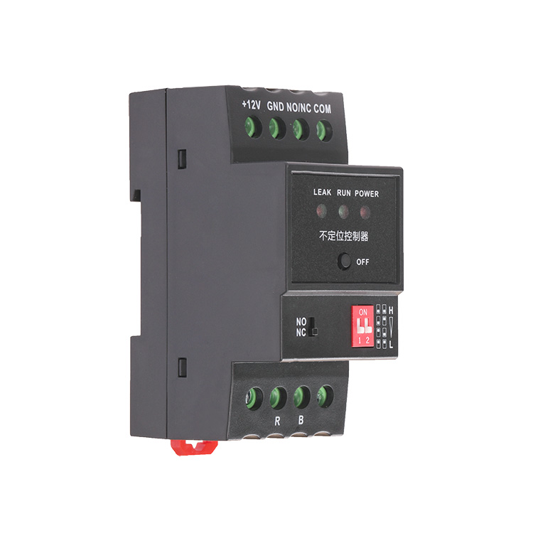
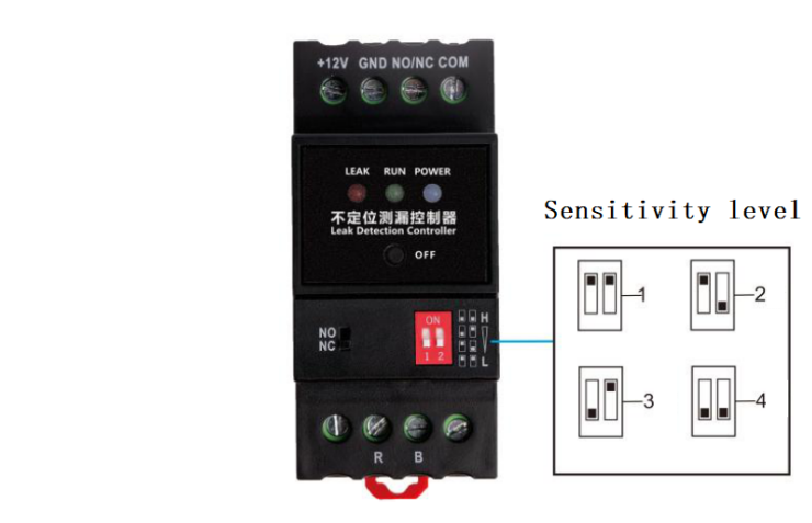
With a 2-bit 4-grade dip switch on the controller panel. Can select different sensitivity according to the requirements of the detection environment (the adjustment range is within 1cm-20cm of the cable length).
Adopt standard industrial modules and DIN rail mounting, all connections can be easily done through terminals. When leakage occurs, the relay act and leakage indicator light up, and the controller automatically restores to normal state after danger elimination, no need manual operation.
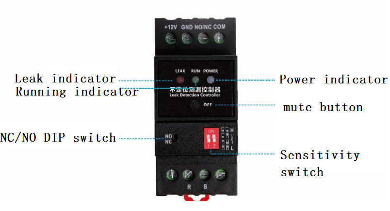
When detects liquid leakage, the LED leakage indicator on the panel is steady on and the internal buzzer gives an alarm sound.
There is a mute button on the controller panel to mute the internal buzzer.
Technical Data
|
Sensing performance |
Response time |
≤1s |
|
Detection distance |
500m |
|
|
Environmental rating |
OperatingTemperature |
-40℃~70℃ |
|
Operating humidity |
0~95%RH(No condensation) |
|
|
Power supply |
Supply voltage |
DC 9~30V(recommend12V DC) |
|
Power Consumption |
≤0.5W |
|
|
Relay |
Contact type |
Dry Contact, 1 set, NC/NO |
|
Load capacity |
120VAC/2A, 24VDC/2A |
|
|
EMC protection grade |
ESD |
Contact discharge±8KV, Air discharge±15KV |
|
Surge |
±4KV |
|
|
EFT |
±4KV |
Operation Principle
XW-DC-02 Simple leak detector connect with sense cables, and the leakage data can be collected through the switch value collection module and uploaded to the host computer. Sensor relay output signal can be used to control peripheral equipment such as acousto-optic alarm, telephone dialer, SMS module, switch value collection module, etc.
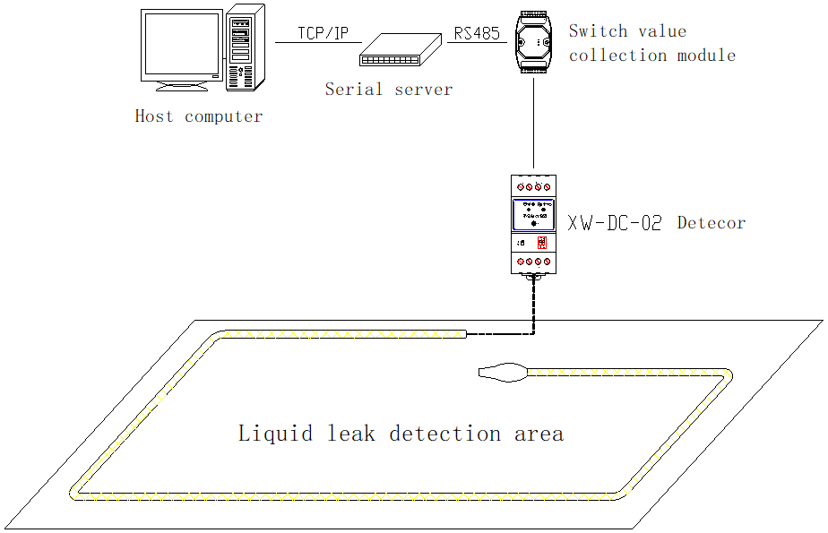
Detection system topology diagram
Installation
Product dimensions (Unit: mm, error: ±0.5mm)
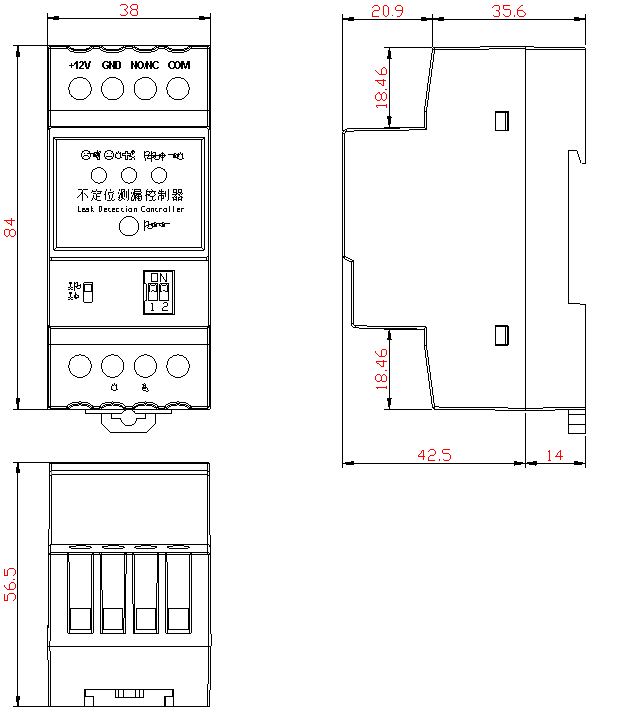
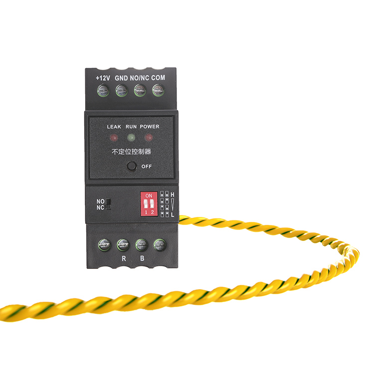
Buttons and indicators
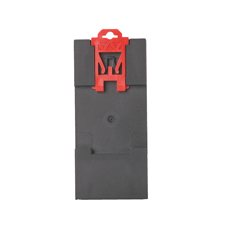
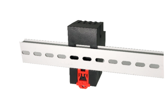
Install the detector in a secure indoor collection box or cabinet where it is easy to maintain and check. Avoid high temperature, high humidity, vibration, corrosive gases, and other electronic interference sources. The detector buckle is mounted on a standard 35 mm DIN rail.
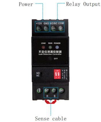
Non-locating leak detection system is composed of detector, outgoing cable, sense cable and related accessories. Connect cables when the power supply of detector is disconnected.
|
Sense cable |
Connect the red and black core wires of the outgoing cable to the wiring terminals R and B of the detector separately, and then lay the sense cables to the detection area. |
|
Relay output |
Output NO/NC contact can be connected to monitoring system, also can be connected to alarm devices to output alarm signal. When controlling high current equipment, it is necessary to add secondary relays to expand the contact load capacity, otherwise the detector may burn out. |
|
Power Supply |
DC 9~30V power input (DC12V is recommended to ensure long-term working stability). If voltage too low, it will not work properly, and if voltage too high, the controller will burn out. |